


Automation Products
-

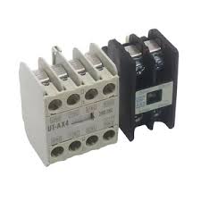
MODEL-AUXILIARY CONTACT FOR MPCB UT-MAL MAKE MITSUBISHI
DELIVERY PERIOD : 1- 2 WEEKS The "MODEL-AUXILIARY CONTACT FOR MPCB UT-MAL MAKE MITSUBISHI" refers to an auxiliary contact unit, specifically designed for Mitsubishi Electric's Motor Protection Circuit Breakers (MPCB) of the UT-MAL series. These auxiliary contacts are used to provide additional signaling or control functionality by indicating the status (open or closed) of the MPCB's main contacts. Here's a breakdown: MPCB (Motor Protection Circuit Breaker): A specialized circuit breaker designed to protect electric motors from various electrical faults like overloads and short circuits. UT-MAL: A specific series or model of Mitsubishi Electric's MPCBs. Auxiliary Contact: A small switch mechanically linked to the main contacts of the MPCB. It opens and closes along with the main contacts, providing a way to remotely monitor or control other circuits. Mitsubishi Electric: A well-known manufacturer of electrical and electronic equipment, including MPCBs and their accessories. In essence, the UT-MAL auxiliary contact unit allows you to: Monitor the MPCB's status: For example, you can use it to signal whether the motor is running or stopped. Interlock other circuits: You can use the auxiliary contact to prevent other devices from operating when the motor is not running, or vice versa. Specific models mentioned in the search results: UT-AX4 2A2B: A Mitsubishi Electric auxiliary contact unit with 2 normally open (NO) and 2 normally closed (NC) contacts. UT-MAXLL 1B: A Mitsubishi Electric auxiliary contact unit with 1 NC contact. UT-MAL 1a, UT-MAL 1b: Possible auxiliary contact units for the UT-MAL MPCB series, with 1 NO and 1 NC contact, respectively. Where to find more information: Mitsubishi Electric's website: You can often find detailed specifications and ordering information for their products on their official website. Technical documentation: Look for the technical catalogs or manuals for the UT-MAL series of MPCBs, which may contain details about compatible auxiliary contact units.
Rs. 2,596.00
-

MODEL-PLC FX5U-80MT/ES MAKE MITSUBISHI
DELIVERY PERIOD : 1- 2 WEEKS Type FX5U Power Supply (V) 100-240 Current Type AC Program Memory 64K STEPS Program Memory Unit FLASH Integrated Digital Inputs 40 Integrated Digital Outputs 40 Integrated Analogue Inputs 2 Output Type TRANSISTOR Output Logic SOURCE Local I/O Points 256 Local + Remote I/O Points 512 Expandable YES Cycle Time LD (ns) 34 Cycle Time MOV (ns) 34 Ethernet Port 1 RS-485 1 Power Consumption (W) 45 Buffer Battery OPTION Protection Class IP10 Min. Ambient Temperature (°C) 0 Max. Ambient Temperature (°C) 55 Series MELSEC IQ-F SERIES Product Dimensions & Weight Depth (mm) 83 Weight (kg) 1,2 Width (mm) 285 Height (mm) 90 Conformity CE COMPLIANT Shipping Approvals ABS,BV,DNV GL,KR,LR,NK,RINA EAC COMPLIANT UL/cUL COMPLIANT UKCA COMPLIANT
Rs. 36,080.40
-

MODEL-PLC FX5-32 ER/ES MAKE MITSUBISHI
DELIVERY PERIOD : 1- 2 WEEKS Series MELSEC IQ-F SERIES Type POWERED I/O MODULE (AC) Power Supply (V) 100-240 Current Type AC Occupied I/O Points on PLC 32 Integrated Digital Inputs 16 Integrated Digital Outputs 16 Output Type RELAY Product Dimensions & Weight Depth (mm) 83 Weight (kg) 0,65 Width (mm) 150 Height (mm) 90 Conformity CE COMPLIANT Shipping Approvals ABS,BV,DNV GL,KR,LR,NK,RINA EAC COMPLIANT UL/cUL COMPLIANT UKCA COMPLIANT
Rs. 14,844.40
-

MODEL-FX5-16ER MAKE MITSUBISHI
DELIVERY PERIOD : 1- 2 WEEKS Series MELSEC IQ-F SERIES Type I/O COMBINED MODULE Power Supply (V) 24 Current Type DC Occupied I/O Points on PLC 16 Integrated Digital Inputs 8 Integrated Digital Outputs 8 Output Type RELAY Product Dimensions & Weight Depth (mm) 83 Weight (kg) 0,21 Width (mm) 40 Height (mm) 90 Conformity CE COMPLIANT Shipping Approvals ABS,BV,DNV GL,KR,LR,NK,RINA EAC COMPLIANT UL/cUL COMPLIANT UKCA COMPLIANT
Rs. 11,200.00
-

MODEL-SERVO MOTOR HG-SR102BK-MAKE MITSUBISHI
DELIVERY PERIOD : 1- 2 WEEKS Series MELSERVO-J4 Type HG-SR Rated Capacity (kW) 1 Rated Torque (Nm) 4,8 Maximum Torque (Nm) 14,3 Rated Speed (rpm) 2000 Maximum Speed (rpm) 3000 Inertia (kg*cm2) 11,6 Brake NO Shaft Type STRAIGHT SHAFT Protection Class IP67 Power Supply (V) 200 Current Type AC Encoder Type 22-BIT Encoder Resolution (p/rev) 4194304
Rs. 84,370.00
-

MODEL-PLC MITSUBISHI FX3U-80MT/ES
Type FX3U Power Supply (V) 100-240 Current Type AC Program Memory 64K STEPS Program Memory Unit RAM Integrated Digital Inputs 40 Integrated Digital Outputs 40 Output Type TRANSISTOR Output Logic SINK Local I/O Points 256 Local + Remote I/O Points 384 Expandable YES Cycle Time LD (ns) 65 Cycle Time MOV (ns) 642 RS-422 1 Power Consumption (W) 50 Buffer Battery YES Protection Class IP10 Min. Ambient Temperature (°C) 0 Max. Ambient Temperature (°C) 55 Series MELSEC-F SERIES Product Dimensions & Weight Depth (mm) 86 Weight (kg) 1,2 Width (mm) 285 Height (mm) 90 Conformity CE COMPLIANT Shipping Approvals ABS,BV,DNV GL,KR,LR,NK,RINA EAC COMPLIANT UKCA COMPLIANT
Rs. 31,500.00
-

MODEL-PLC MITSUBISHI FX3U-64MT/ES
DELIVERY PERIOD : 1- 2 WEEKS Type FX3U Power Supply (V) 100-240 Current Type AC Program Memory 64K STEPS Program Memory Unit RAM Integrated Digital Inputs 32 Integrated Digital Outputs 32 Output Type TRANSISTOR Output Logic SINK Local I/O Points 256 Local + Remote I/O Points 384 Expandable YES Cycle Time LD (ns) 65 Cycle Time MOV (ns) 642 RS-422 1 Power Consumption (W) 45 Buffer Battery YES Protection Class IP10 Min. Ambient Temperature (°C) 0 Max. Ambient Temperature (°C) 55 Series MELSEC-F SERIES Product Dimensions & Weight Depth (mm) 86 Weight (kg) 1 Width (mm) 220 Height (mm) 90 Conformity CE COMPLIANT Shipping Approvals ABS,BV,DNV GL,KR,LR,NK,RINA EAC COMPLIANT UKCA COMPLIANT
Rs. 27,000.00
-

MODEL-COMMU. PCB MITSUBISHI FX3U-80MT/ES
DELIVERY PERIOD : 1- 2 WEEKS Overview AC Power Supply/DC Input TypeInput: 40 points 24 V DC sink/sourceOutput: 40 points Transistor sink Conformance standard UL cUL CE(EMC) CE(LVD) CE(RoHS) CE(Battery) KC(EMC) LR NK DNV ABS RINA BV KR Sales status On sale Merit If considering high speed, high functions, and expandability ・Controllable I/O: Up to 384 points (for remote I/O configuration of CC-Link, AnyWire)・3rd generation micro PLC. New highly functional machine equipped with speed, capacity, performance, and functions.・The built-in functions, such as the industry's highest level of high-speed processing and positioning, have been greatly improved.・A maximum of 384 I/O points, including remote I/O, can be controlled. Various special function devices for FX2N are connectable. Operation control system Input/output control system Programming language Program memory Max. memory capacity Built-in memory capacity/type Memory cassette (Option) Writing function during running Protection Real-time clock Clock function Kinds of instructions Basic instructions Applied instructions Processing speed Basic instructions Applied instructions No. of input/output points No. of input points No. of output points Remote I/O number of points CC-Link AnyWireASLINK AS-i Total number of points Device Input/output relay Input relay Output relay Auxiliary relay For general For keeping For keeping (battery backup fixed area) For special State Initial state For general For keeping 1 For annunciator For keeping 2 Timer (on delay) 100 ms 100 ms (for subroutine/interruption subroutine) 10 ms 1 ms accumulating type 100 ms accumulating type 1 ms Counter 16 bits up 16 bits up (keeping) 32 bits up or down 32 bits up or down (keeping) High-speed counter Data register (32 bits when paired) 16 bits for general 16 bits for keeping 16 bits for keeping (File register) 16 bits for special 16 bits for index Extension register Extension file register Pointer For branching of JUMP and CALL Input interruption and input delay interruption Timer interruption Counter interruption Nesting Constant Decimal number (K) Hexadecimal number (H) Real number (E) Character string (" ") Power supply specifications Rated voltage Allowable supply voltage range Frequency rating Allowable instantaneous power failure time Power fuse Rush current Power consumption 24 V DC service power supply 5 V DC built-in power supply Input specifications No. of input points Input connection type Input type Input signal voltage Input impedance X000 to X007 X010 or more Input signal current X000 to X007 X010 or more ON input sensitivity current X000 to X007 X010 or more OFF input sensitivity current Input response time Input signal form Input circuit insulation Indication of input operation Input circuit configuration Output specifications No. of output points Output connection type Output type External power supply Max. load Resistance load Inductive load Min. load Open circuit leakage current ON voltage Response time OFF→ON ON→OFF Insulation of circuit Indication of output operation Output circuit configuration Stored program repetitive operation system (dedicated LSI) with interruption function Batch processing system (when END instruction is executed), Input/output refresh instruction and pulse catch function are provided. Relay symbol system + step-ladder system (SFC notation possible) 64000 stepsUp to 64000 steps, including comment and file registers 64000-step (Symbolic information can be stored. Supported in Ver. 3.00 or later.)/RAM (backed up by built-in lithium battery)Battery life: Approx. 5 years [Ver. 3.00 or later]・FX3U-FLROM-1M (2000/4000/8000/16000/32000/64000 steps, loader function, symbolicinformation can be stored in the dedicated area (1300 kB).)[Ver. 2.20]・FX3U-FLROM-64L (2000/4000/8000/16000/32000/64000 steps, loader function)・FX3U-FLROM-64 (2000/4000/8000/16000/32000/64000 steps, no loader function)・FX3U-FLROM-16 (2000/4000/8000/16000 steps, no loader function) Provided (Program can be modified while the PLC is running.) Password protection provided (with entry code function) Built-in1980 to 2079 (with correction for leap year)2- or 4-digit year, accuracy within ±45 seconds/month at 25°C [Ver. 2.30 or later]・Sequence instructions: 29・Step-ladder instructions: 2[Former than Ver. 2.30]・Sequence instructions: 27・Step-ladder instructions: 2 219 kinds 498 instructions 0.065 μs/instruction 0.642 μs to several hundred μs/instruction (1) 248 points or less (Extension combined number) (1)+(2) total number of points is 256 or less. (2) 248 points or less (Extension combined number) (1)+(2) total number of points is 256 or less. (3) 256 points or less (224 points or less when the FX2N-16CCL-M is used.)*The total number of remote I/O points in CC-Link and AnyWireASLINK must be 256 points or less. (3) 128 points or less*The total number of remote I/O points in CC-Link and AnyWireASLINK must be 256 points or less. (3) 248 points or less (1)+(2)+(3) total number of points is 384 or less. (Extension combined number) X000 to X367: 248 points (octal) Extension combined number Y000 to Y367: 248 points (octal) Extension combined number M0 to M499: 500 pointsThe retentive status can be changed by parameter settings. M500 to M1023: 524 pointsThe retentive status can be changed by parameter settings. M1024 to M7679: 6656 pointsThis retentive status is a battery backup fixed area. The area characteristics cannot be changed. M8000 to M8511: 512 points S0 to S9: 10 pointsThe retentive status can be changed by parameter settings. S10 to S499: 490 pointsThe retentive status can be changed by parameter settings. S500 to S899: 400 pointsThe retentive status can be changed by parameter settings. S900 to S999: 100 pointsThe retentive status can be changed by parameter settings. S1000 to S4095: 3096 pointsThis retentive status is a battery backup fixed area. The area characteristics cannot be changed. T0 to T191: 192 points (0.1 to 3,276.7 sec) T192 to T199: 8 points (0.1 to 3,276.7 sec) T200 to T245: 46 points (0.01 to 327.67 sec) T246 to T249: 4 points (0.001 to 32.767 sec)This retentive status is a battery backup fixed area. The area characteristics cannot be changed. T250 to T255: 6 points (0.1 to 3,276.7 sec)This retentive status is a battery backup fixed area. The area characteristics cannot be changed. T256 to T511: 256 points (0.001 to 32.767 sec) C0 to C99: 100 points (Counting from 0 to 32,767)The retentive status can be changed by parameter settings. C100 to C199: 100 points (Counting from 0 to 32,767)The retentive status can be changed by parameter settings. C200 to C219: 20 points (Counting from -2,147,483,648 to +2,147,483,647)The retentive status can be changed by parameter settings. C220 to C234: 15 points (Counting from -2,147,483,648 to +2,147,483,647)The retentive status can be changed by parameter settings. [32 bits High speed up/down (keeping)]Up to 8 points can be used in range from C235 to C255.・Hardware counter1-phase: 100 kHz, 10 kHz2-phase: 50 kHz (1 edge count), 50 kHz (4 edge count)・Software counter1-phase: 40 kHz2-phase: 40 kHz (1 edge count), 10 kHz (4 edge count)There are restrictions on the points that can be used and input frequencies depending on the conditions used. D0 to D199: 200 pointsThe retentive status can be changed by parameter settings. D200 to D511: 312 pointsThe retentive status can be changed by parameter settings. D512 to D7999: 7488 points (D1000 and later can be set as file register points in 500-point units)This retentive status is a battery backup fixed area. The area characteristics cannot be changed. D8000 to D8511: 512 points V0 to V7, Z0 to Z7: 16 points [16 bits]R0 to R32767: 32768 pointsThis retentive status is a battery backup fixed area. The area characteristics cannot be changed. [16 bits]ER0 to ER32767: 32768 pointsUsable only when memory cassette is mounted P0 to P4095: 4096 points (For CJ instructions and CALL instructions, P63 jumps to END instruction) I00□ to I50□: 6 points I6□□ to I8□□: 3 points I010 to I060: 6 points (For HSCS instructions) [For master control]N0 to N7: 8 points (For MC instructions) 16 bits: -32,768 to +32,76732 bits: -2,147,483,648 to +2,147,483,647 16 bits: 0 to FFFF32 bits: 0 to FFFFFFFF 32 bits: -1.0 × 2128 to -1.0 × 2-126, 0, 1.0 × 2-126 to 1.0 × 2128Decimal-point and exponential notations are possible. Designation by characters enclosed with " "Up to 32 one-byte characters can be used for a constant in an instruction. 100 to 240 V AC 85 to 264 V AC 50/60 Hz Operation can be continued upon occurrence of instantaneous power failure for 10 ms or less.When the supply voltage is 200 V AC, the time can be change to 10 to 100 ms by editing the user program. 250 V 5 A 30 A max. 5 ms or less/100 V AC, 65 A max. 5 ms or less/200 V AC 50 WThese power consumption values are maximum values which apply to the main unit's 24 V DC service power supply when there are input/output extension blocks and special function units/blocks. 600 mA or less 500 mA or lessThe power supply is not for external use.The current capacity specified above is for the input/output extension blocks, special function blocks, special adapters and expansion boards. 40 points Removable terminal block (M3 screw) Sink/source 24 V DC ±10% X000 to X005: 3.9 kΩX006, X007: 3.3 kΩ 4.3 kΩ X000 to X005: 6 mA/24 V DCX006, X007: 7 mA/24 V DC 5 mA/24 V DC X000 to X005: 3.5 mA or moreX006, X007: 4.5 mA or more 3.5 mA or more 1.5 mA or less Approx. 10 msX000 to X017 (up to the main unit built-in number) have built-in digital filters, which can be changed to 0 to 60 ms in 1 ms increments using the application instructions or D8020.The following is applied when 0 is set.X000 to X005: 5μsX006, X007: 50μsX010 to X017: 200μs No-voltage contact inputSink: NPN open collector transistorSource: PNP open collector transistor Photocoupler insulation LED is lit when input is on 40 points Removable terminal block (M3 screw) Transistor/sink output 5-30 V DC 0.5 A or less/1 output pointThe total load current per common terminal should be the following value.1 output point/common terminal: 0.5 A or less4 output points/common terminal: 0.8 A or less8 output points/common terminal: 1.6 A or less 12 W/24 V DC - 0.1 mA or less/30 V DC 1.5 V or less Y000 to Y002: 5 μs or less/10 mA or more (5-24 V DC)Y003 or more: 0.2 ms or less/200 mA or more (at 24 V DC) Y000 to Y002: 5 μs or less/10 mA or more (5-24 V DC)Y003 or more: 0.2 ms or less/200 mA or more (at 24 V DC) Photocoupler insulation When photocoupler is driven, LED on panel is lit. Function specifications Built-in high-speed counter function 1-phase 1-count input 1-phase 2-count input 2-phase 2-count input Built-in pulse output and positioning function Number of control axes Maximum frequency Programming language Compatible main units Pulse output instruction Positioning instruction [C235 to C240]Up to 6 points: Up to 100 kHzWhen used High-speed comparison SET/RESET: 40 kHzWhen used High-speed zone compare HSZ: 40 - (number of instruction)[C244(OP), C245(OP)]Up to 2 points: Up to 10 kHzWhen used High-speed comparison SET/RESET: 10 kHzWhen used High-speed zone compare HSZ: 40 - (number of instruction)[C241 to C245]Up to 3 points: Up to 40 kHzWhen used High-speed comparison SET/RESET: 40 kHzWhen used High-speed zone compare HSZ: 40 - (number of instruction)When using the High-speed comparison SET/RESET, the maximum total frequency that the PLC can process (multiplied by 4 for 2-phase 4-edge counter) is 80 kHz.When using the High-speed zone compare HSZ, the total frequency processed by the PLC (multiplied by four times the input frequency for the two-phase 4-edge counter) is the maximum frequency obtained by "80 kHz - 1.5 x the number of times the HSZ instruction is used.” [C246, C248(OP)]Up to 2 points: Up to 100 kHzWhen used High-speed comparison SET/RESET: 40 kHzWhen used High-speed zone compare HSZ: 40 - (number of instruction)[C247 to C250]Up to 2 points: Up to 40 kHzWhen used High-speed comparison SET/RESET: 40 kHzWhen used High-speed zone compare HSZ: 40 - (number of instruction)When using High-speed comparison SET/RESET, the maximum total frequency that the PLC can process (multiplied by 4 for 2-phase 4-edge counter) is 80 kHz.When using High-speed zone compare HSZ, the total frequency processed by the PLC (multiplied by four times the input frequency for the two-phase 4-edge counter) is the maximum frequency obtained by "80 kHz - 1.5 x the number of times the HSZ instruction is used.” [C251, C253]Up to 2 points: Up to 100 kHzWhen used High-speed comparison SET/RESET: 40 kHzWhen used High-speed zone compare HSZ: 40 - (number of instruction) [C252, C253(OP), C254, C255]Up to 2 points: Up to 40 kHzWhenC used High-speed comparison SET/RESET: 40 kHzWhen used High-speed zone compare HSZ: 40 - (number of instruction)When using High-speed comparison SET/RESET, the maximum total frequency that the PLC can process (multiplied by 4 for 2-phase 4-edge counter) is 80 kHz.When using High-speed zone compare HSZ, the total frequency processed by the PLC (multiplied by four times the input frequency for the two-phase 4-edge counter) is the maximum frequency obtained by "80 kHz - 1.5 x the number of times the HSZ instruction is used.” 3 independent axes 100 kHz Sequence program Transistor output type main unit ・Pulse Y Output (PLSY)・Acceleration/Deceleration Setup (PLSR)Pulse output form: Pulse train (The direction is controlled with the sequence.) ・ABS Absolute current value read ([D]ABS)・DOG Search Zero Return [DSZR]・Zero Return [ZRN] (no DOG search function)Decelerates when near-point DOG is ON, Stops when near-point DOG is OFF. (This is different from the zero return operation by counting the zero point signal.)・Variable speed pulse output [PLSV]・Drive to increment [DRVI]・Drive to Absolute [DRVA]・Interrupt Positioning [DVIT]・Batch data positioning mode ([D]TBL)Pulse output form: Pulse train + direction General specifications Ambient temperature Ambient humidity Vibration resistance Installed on DIN rail Frequency: 10 to 57 Hz Frequency: 57 to 150 Hz Direct installing Frequency: 10 to 57 Hz Frequency: 57 to 150 Hz Shock resistance Noise resistance Dielectric withstand voltage Insulation resistance Grounding Working atmosphere Working altitude 0 to 55°C (32 to 131°F) when operating and -25 to 75°C (-13 to 167°F) when stored 5 to 95%RH (no condensation) when operating Half amplitude: 0.035mm Sweep Count for X, Y, Z: 10 times (80 min in each direction)The criterion is shown in IEC61131-2. Acceleration: 4.9 m/s2 Sweep Count for X, Y, Z: 10 times (80 min in each direction)The criterion is shown in IEC61131-2. Half amplitude: 0.075 mm Sweep Count for X, Y, Z: 10 times (80 min in each direction)The criterion is shown in IEC61131-2. Acceleration: 9.8 m/s2 Sweep Count for X, Y, Z: 10 times (80 min in each direction)The criterion is shown in IEC61131-2. 147 m/s2 Acceleration, Action time: 11 ms, 3 times by half-sine pulse in each direction X, Y, and ZThe criterion is shown in IEC61131-2. By noise simulator at noise voltage of 1,000 Vp-p, noise width of 1 μs, rise time of 1 ns and period of 30 to 100 Hz Perform dielectric withstand voltage test at the following voltage between each terminals and the main unit ground terminal.Between power supply terminal (AC power supply) and ground terminal: 1.5 kV AC for 1 minBetween 24 V DC service power supply connected to input terminal (24 V DC) and ground terminal: 500 V AC for 1 minBetween output terminal (transistor) and ground terminal: 500 V AC for 1 min Perform insulation resistance test at the following voltage between each terminals and the main unit ground terminal.Between power supply terminal (AC power supply) and ground terminal: 5 MΩ or higher by 500 V DC insulation resistance testerBetween 24 V DC service power supply connected to input terminal (24 V DC) and ground terminal: 5 MΩ or higher by 500 V DC insulation resistance testerBetween output terminal (transistor) and ground terminal: 5 MΩ or higher by 500 V DC insulation resistance tester Class D grounding (grounding resistance: 100 Ω or less)(Common grounding with a heavy electrical system is not allowed)Ground the PLC independently or jointly. Free from corrosive or flammable gas and excessive conductive dusts 2000 m or lessDo not use the PLC under pressure higher than the atmospheric pressure. Doing so may damage the PLC.
Rs. 32,500.00
-

MODEL-PLC MITSUBISHI FX3U-48MT/ES-A
DELIVERY PERIOD : 1- 2 WEEKS Type FX3U Power Supply (V) 100-240 Current Type AC Program Memory 64K STEPS Program Memory Unit RAM Integrated Digital Inputs 24 Integrated Digital Outputs 24 Output Type TRANSISTOR Output Logic SINK Local I/O Points 256 Local + Remote I/O Points 384 Expandable YES Cycle Time LD (ns) 65 Cycle Time MOV (ns) 642 RS-422 1 Power Consumption (W) 40 Buffer Battery YES Protection Class IP10 Min. Ambient Temperature (°C) 0 Max. Ambient Temperature (°C) 55 Series MELSEC-F SERIES Product Dimensions & Weight Depth (mm) 86 Weight (kg) 0,85 Width (mm) 182 Height (mm) 90 Conformity CE COMPLIANT Shipping Approvals ABS,BV,DNV GL,KR,LR,NK,RINA EAC COMPLIANT UKCA COMPLIANT
Rs. 24,300.00
-

MODEL-CC LINK REMOTE OUTPUT UNIT AJ65SBTB1-16T1
DELIVERY PERIOD : 1- 2 WEEKS Series CC-LINK Type REMOTE TRANSISTOR OUTPUT Power Supply (V) 24 Current Type DC Occupied Stations 1 Integrated Digital Outputs 16 Output Type TRANSISTOR Output Logic SINK Rated Load Voltage (VDC) 12/24 Wiring SCREW Int. Current Consumption (A) 0,05
Rs. 11,328.00
-

MODEL-CC LINK REMOTE INPUT UNIT AJ65SBTB1-32D MAKE MITSUBISHI
DELIVERY PERIOD : 1- 2 WEEKS Series CC-LINK Type REMOTE DC INPUT Power Supply (V) 24 Current Type DC Occupied Stations 1 Integrated Digital Inputs 32 Rated Input Voltage (VDC) 24 Wiring SCREW Int. Current Consumption (A) 0,045 Product Dimensions & Weight Depth (mm) 40 Weight (kg) 0,25 Width (mm) 179 Height (mm) 50 Conformity CE COMPLIANT EAC COMPLIANT UL/cUL COMPLIANT UKCA COMPLIANT
Rs. 19,116.00
-

MODEL-GOT GT2104-RTBD MAKE MITSUBISHI
DELIVERY PERIOD : 1- 2 WEEKS The GT2104-RTBD is a Human Machine Interface (HMI) from Mitsubishi Electric's GOT2000 series, specifically a compact, programmable terminal. It features a 4.3-inch TFT color display with a resolution of 480x272 pixels and 65,536 colors. This HMI offers various communication interfaces like RS-232, RS-422/485, Ethernet, and USB. It also has an SD card slot for data storage. Key Features: Compact Design: The GT2104-RTBD is designed to be compact, making it suitable for applications where space is limited. Touchscreen Interface: It utilizes a resistive film touch panel for user input. Communication: It supports multiple communication protocols, including RS-232, RS-422/485, Ethernet, and USB. Display: The 4.3-inch color TFT display provides clear visuals for monitoring and controlling processes. Storage: It has an SD card slot for storing data, logs, and other relevant information. Power Supply: It requires a 24V DC power supply. Environmental Tolerance: It can operate in temperatures ranging from 0°C to 55°C (32°F to 131°F) and humidity levels from 10% to 90% (non-condensing). Applications: The GT2104-RTBD is commonly used in industrial automation for human-machine interfaces, allowing operators to interact with and monitor various machines and processes. It's often found in manufacturing, packaging, and other industries where real-time control and monitoring are essential.
Rs. 24,000.00