Mitsubishi
-
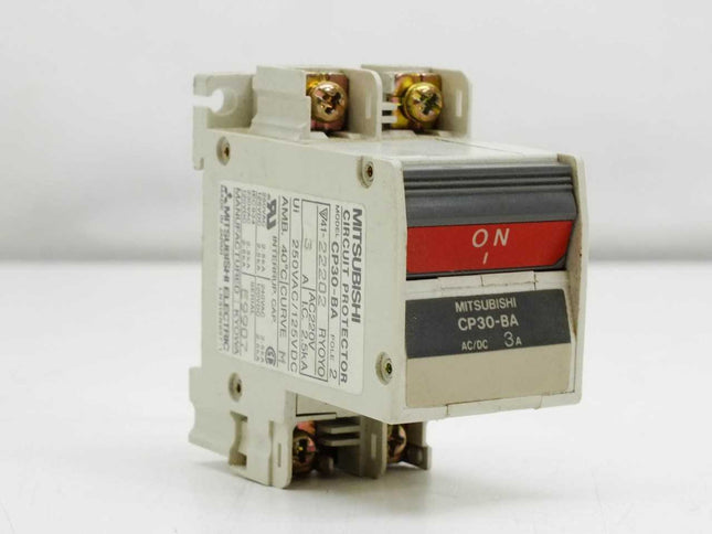
MODEL-MCB-3A CP30BA MAKE MITSUBISHI 2 POLE AC/DC
DELIVERY PERIOD : 1-2 WEEKS [Type] Circuit Protector[Series Name] CP SeriesFrame A: 30Model: CP30-BA 2P 1-MPoles: 2[Rated Current (A)] 3[Rated insulation voltage (V)] 250[Rated impulse resistance voltage (kV)] 2.5[Current type] AC/DC[Reverse connection] Yes[Open and close life (times)]Mechanical 10000Electrical 6000[Standard Ambient Temperature] 40 (T40)[Internal Circuit] Series[Characteristics] Medium speedPull off system: Medium speed[Connection method] Screw terminalOperating Method: S-type (IEC 60934)[Pull off free/Operating system] Trip-free (IEC 60934)[External Dimensions (mm)]a 35b 73c 65ca 65Product Weight: 0.3 lbs (0.16 kg).[Installation Method]Surface mountIEC 35mm Rail MountFlush Mount[Marine Association Certified] NK acquired
Rs. 5,310.00
-
MODEL-Q06UDEHCPU MAKE MITSUBISHI
DELIVERY PERIOD : 1-2 WEEKS Series MELSEC-Q SERIES Type UNIVERSAL MODEL QCPU Program Memory 60K Program Memory Unit STEPS Local I/O Points 4.096 Local + Remote I/O Points 8.192 Cycle Time LD (ns) 9,5 Cycle Time MOV (ns) 19 USB 1 Ethernet Port 1 Buffer Battery YES Int. Current Consumption (A) 0,39 Product Dimensions & Weight Depth (mm) 89,3 Weight (kg) 0,22 Width (mm) 27,4 Height (mm) 98 Conformity CE COMPLIANT Shipping Approvals ABS,BV,DNV GL,LR,NK,RINA EAC COMPLIANT UL/cUL COMPLIANT UKCA COMPLIANT
Rs. 88,264.00
-
MODEL-SERVO MOTOR HF-SP202B MAKE MITSUBISHI
DELIVERY PERIOD : 1-2 WEEKS Condition: Used Model: HF-SP202B Brand: Mitsubishi Made In: Japan Input: 3Ph 132V 10A Output: 2kw (2000w) RPM: 2000 Weight: 17.1kg Item code: SM23
Rs. 59,236.00
-
MODEL-DRIVE MITSUBISHI-FREQROL D700
DELIVERY PERIOD : 1-2 WEEKS Input Phase 3 - Phase Brand Mitsubishi Model Name/Number FR-D700 Series Application Factory Automation Motor Power 0.4 kW to 7.5 kW Input Voltage 380-480 V Input Frequency 50 to 60 Hz Motor RPM 1400 RPM Degree of Protection IP20 Output frequency 0.2 - 400 Hz Mitsubishi AC Drive FR-D700 Series, The user-friendliness of the FR-D700 series makes these units a particularly good choice for standard applications. Entering drive parameters and settings is quick and easy with the one-touch Digital Dial on the integrated control panel, saving time and cutting costs. The FR-D700 series is compliant to the EU Machinery Directive without the addition of previously required external devices. Operation of an external Emergency Stop device results in a highly reliable immediate shutoff of the D700's output to the motor. This safety stop function conforms to the following standards.Features: Spring clamp terminal (control circuit terminal) Long-life design Leading life check function Quick setup with the setting dial Enclosure surface operation panel FR-PA07 (option) Noise filter option which is compatible with EMC Directive (EN61800-3 2nd Environment Category C3) is available RoHS Directive compliant Complies with UL, cUL, EC Directives (CE marking) as a standard model Filterpack FR-BFP2 (option) Easy replacement of cooling fan Easy setting from a personal computer using the FR Configurator (option) Easily replaceable compact body Model Range: FR-D720S-008SC-EC FR-D720S-014SC-EC FR-D720S-025SC-EC FR-D720S-042SC-EC FR-D720S-070SC-EC FR-D720S-100SC-EC FR-D740-012-E16 FR-D740-022-E16 FR-D740-036-E16 FR-D740-050-E16 FR-D740-080-E16 FR-D740-120-E16 FR-D740-160-E16
Rs. 23,364.00
-
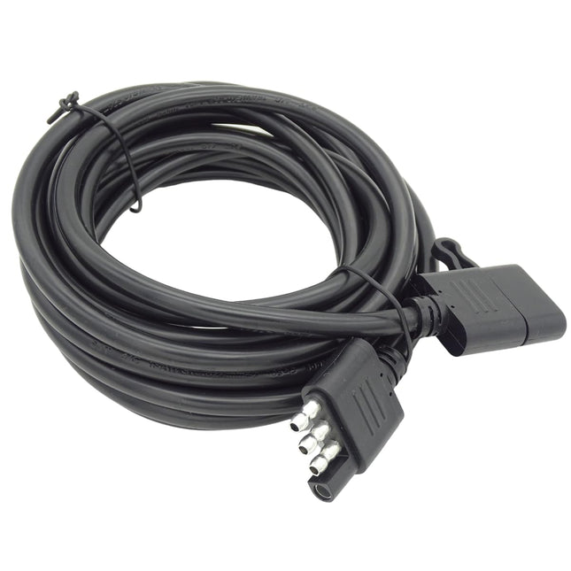
MODEL-MR-BKS2CBL03M-A2-L MAKE MITSUBISHI
DELIVERY PERIOD : 1-2 WEEKS The part number MR-BKS2CBL03M-A2-L refers to a Mitsubishi Electric cable designed for electromagnetic brakes, specifically for HF-KP/HF-MP series servo motors. It is a 0.3-meter cable with an IP55 rating, and the cable lead is in the opposite direction of the motor shaft. Here's a breakdown: MR-BKS2CBL03M-A2-L: This is the specific model number for this Mitsubishi Electric cable. Mitsubishi Electric: This indicates the manufacturer of the cable. Electromagnetic Brake Cable: The cable is designed for use with electromagnetic brakes on servo motors. HF-KP/HF-MP Series: This specifies the type of servo motors compatible with this cable. 0.3M: The cable length is 0.3 meters. IP55: This refers to the Ingress Protection rating, indicating a degree of protection against dust and water. Opposite of motor shaft: This describes the orientation of the cable lead relative to the motor shaft.
Rs. 1,829.00
-
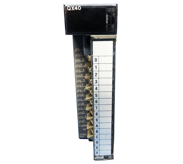
MODEL-QX40 MITSUBISHI 16 POINT/1 COMMON
DELIVERY PERIOD : 1-2 WEEKS FA-MOD PLC: Digital Input Module Series MELSEC-Q SERIES Type DC INPUT (PLUS COMMON) Occupied I/O Points on PLC 16 Integrated Digital Inputs 16 Rated Input Voltage (VDC) 24 Wiring SCREW Int. Current Consumption (A) 0,05 Product Dimensions & Weight Depth (mm) 90 Weight (kg) 0,16 Width (mm) 27,4 Height (mm) 98 Conformity CE COMPLIANT Shipping Approvals ABS,BV,DNV GL,LR,NK,RINA EAC COMPLIANT UL/cUL COMPLIANT UKCA COMPLIANT
Rs. 7,316.00
-
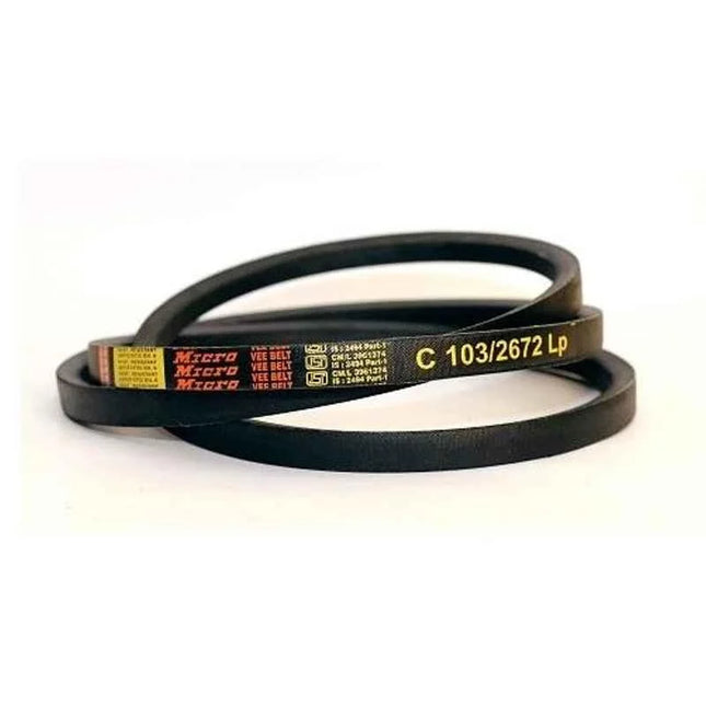
MODEL-V-BELT B-156 MAKE MITSUBISHI
DELIVERY PERIOD : 1-2 WEEKS Product Specifications Brand Mitsubishi Cross Section B Height 11 mm Item Code B156 Top Width 16.5 mm Pitch Length 156 inch Inside Circumference 3962 mm Linear Speed 30 m/s Notes Images are for reference purpose only, Actual Product may vary Operating Temperature -40 to 70 deg C Pulley Diameter 150 mm Country of origin India Manufacturer Details 1st Floor, Street No. 1, Freinds Colony G.T. Road, Shahdara. NEW DELHI DELHI, East Delhi, Delhi-110095 Packer Details 1st Floor, Street No. 1, Freinds Colony G.T. Road, Shahdara. NEW DELHI DELHI, East Delhi, Delhi-110095 Common/Generic Name V Belt Dimensions LxWxH 47x8x66 cm Weight 1 kg
Rs. 1,125.72
-
MODEL-FX3U-64CCL CC LINK CARD MAKE MITSUBISHI
DELIVERY PERIOD : 1-2 WEEKS Basic information Overview Intelligent device station for CC-Link Conformance standard UL cUL CE(EMC) CE(RoHS) KC(EMC) Sales status On sale Merit CC-Link system interface block • The FX3U-64CCL type CC-Link interface block is a special function block that connects the FX5U/FX5UC CPU module and the FX3G/FX3U/FX3GC/FX3UC PLC to the CC-Link. (CC-Link V2 compatible)The FX3U-64CCL operates as a CC-Link intelligent device station. Only one FX3U-64CCL can be connected to a single PLC main module.• Using GX Developer, the FX5U/FX5UC CPU module and FX3G/FX3U/FX3GC/FX3UC PLC main unit to which the FX3U-64CCL is connected can be accessed from the Q master station/local station via CC-Link. (Supported with GX Developer Ver. 8.76E or later)
Rs. 17,464.00
-
MODEL-SERVO DRIVE TYPE-MR-J2S-200CP MAKE MITSUBISHI
DELIVERY PERIOD ; 1-2 WEEKS Primary brand Mitsubishi Electric Main function AC servo drive Product series / family name MELSERVO J2S series Sub-range name MR-J2 series Functions AC motion servo drive / amplifierbuilt-in positioning functionsine wave PWM control/current control method Design built-in dynamic brakebuilt-in position functionforced ventilation cooling Supply voltage (AC) 200Vac-230Vac (200V class; 220Vac / 230Vac) Type of network 3-phase input (3P) Rated active power (kW) 2000W / 2kW Protection functions overcurrent shut-offregeneration overvoltage shut-offoverload shut-off (electronic thermal) servo motor overheat protectionencoder fault protectionregeneration fault protectionundervoltage/sudden power outage protectionoverspeed protectionexcessive error protection Communication protocol RS-422RS-485 Digital inputs 1 x digital input (24Vdc; sink/source) (LSP)1 x digital input (24Vdc; sink/source) (LSN)1 x digital input (24Vdc; sink/source) (DOG)1 x digital input (24Vdc; sink/source) (SON)1 x digital input (24Vdc; sink/source) (MD0)1 x digital input (24Vdc; sink/source) (ST1)1 x digital input (24Vdc; sink/source) (ST2)1 x digital input (24Vdc; sink/source) (DI0)1 x digital input (24Vdc; sink/source) (DI1) Digital outputs 1 x digital output (rly. contact type) (ALM)1 x digital output (rly. contact type) (ZP)1 x digital output (rly. contact type) (CPO)1 x digital output (rly. contact type) (MEND)1 x digital output (rly. contact type) (RD) Analog inputs 1 x analog input (0-10Vdc) (TLA)1 x analog input (-10...+10Vdc) (VC) Dimensions H168mm x W90mm x D195mm Net Height (mm) 168 mm Net Width (mm) 90 mm Net Depth (mm) 195 mm Ambient air temperature for operation 0...+55 °C Ambient air temperature for storage -20°C...+65 °C Technical compatibility with HC-SFS seriesHC-LFS series Order code / Manufacturer SKU MR-J2S-200CP
Rs. 87,320.00
-
MODEL-FX2N-32ER MAKE MITSUBISHI
DELIVERY PERIOD : 1-2 WEEKS FA-COM PLC: Digital I/O Module Series MELSEC-F SERIES Type FX2N Power Supply (V) 100-240 Current Type AC Occupied I/O Points on PLC 32 Integrated Digital Inputs 16 Integrated Digital Outputs 16 Output Type RELAY Product Dimensions & Weight Depth (mm) 87 Weight (kg) 0,65 Width (mm) 15 Height (mm) 90 Conformity CE COMPLIANT Shipping Approvals ABS,BV,DNV GL,KR,LR,RINA EAC COMPLIANT UL/cUL COMPLIANT UKCA COMPLIANT
Rs. 17,346.00
-
MODEL-BATTERY MR-BAT 6V 1SET MITSUBISHI
DELIVERY PERIOD : 1-2 WEEKS Voltage 6 V Battery Type Lithium Ion Brand Mitsubishi Model Name/Number MR-BAT6V1SET-A Battery Capacity 1650MAH MODEL: MR-BAT6V1SET-ABRAND: MITSUBISHIVOLTAGE: 6VAPPLICATION: MITSUBISHI MACHINESORIGIN: JAPAN
Rs. 885.00
-
MODEL-PLC FX3U-48MT.ES MAKE MITSUBISHI
DELIVERY PERIOD : 1-2 WEEKS Operation control system Input/output control system Programming language Program memory Max. memory capacity Built-in memory capacity/type Memory cassette (Option) Writing function during running Protection Real-time clock Clock function Kinds of instructions Basic instructions Applied instructions Processing speed Basic instructions Applied instructions No. of input/output points No. of input points No. of output points Remote I/O number of points CC-Link AnyWireASLINK AS-i Total number of points Device Input/output relay Input relay Output relay Auxiliary relay For general For keeping For keeping (battery backup fixed area) For special State Initial state For general For keeping 1 For annunciator For keeping 2 Timer (on delay) 100 ms 100 ms (for subroutine/interruption subroutine) 10 ms 1 ms accumulating type 100 ms accumulating type 1 ms Counter 16 bits up 16 bits up (keeping) 32 bits up or down 32 bits up or down (keeping) High-speed counter Data register (32 bits when paired) 16 bits for general 16 bits for keeping 16 bits for keeping (File register) 16 bits for special 16 bits for index Extension register Extension file register Pointer For branching of JUMP and CALL Input interruption and input delay interruption Timer interruption Counter interruption Nesting Constant Decimal number (K) Hexadecimal number (H) Real number (E) Character string (" ") Power supply specifications Rated voltage Allowable supply voltage range Frequency rating Allowable instantaneous power failure time Power fuse Rush current Power consumption 24 V DC service power supply 5 V DC built-in power supply Input specifications No. of input points Input connection type Input type Input signal voltage Input impedance X000 to X007 X010 or more Input signal current X000 to X007 X010 or more ON input sensitivity current X000 to X007 X010 or more OFF input sensitivity current Input response time Input signal form Input circuit insulation Indication of input operation Input circuit configuration Output specifications No. of output points Output connection type Output type External power supply Max. load Resistance load Inductive load Min. load Open circuit leakage current ON voltage Response time OFF→ON ON→OFF Insulation of circuit Indication of output operation Output circuit configuration Stored program repetitive operation system (dedicated LSI) with interruption function Batch processing system (when END instruction is executed), Input/output refresh instruction and pulse catch function are provided. Relay symbol system + step-ladder system (SFC notation possible) 64000 stepsUp to 64000 steps, including comment and file registers 64000-step (Symbolic information can be stored. Supported in Ver. 3.00 or later.)/RAM (backed up by built-in lithium battery)Battery life: Approx. 5 years [Ver. 3.00 or later]・FX3U-FLROM-1M (2000/4000/8000/16000/32000/64000 steps, loader function, symbolicinformation can be stored in the dedicated area (1300 kB).)[Ver. 2.20]・FX3U-FLROM-64L (2000/4000/8000/16000/32000/64000 steps, loader function)・FX3U-FLROM-64 (2000/4000/8000/16000/32000/64000 steps, no loader function)・FX3U-FLROM-16 (2000/4000/8000/16000 steps, no loader function) Provided (Program can be modified while the PLC is running.) Password protection provided (with entry code function) Built-in1980 to 2079 (with correction for leap year)2- or 4-digit year, accuracy within ±45 seconds/month at 25°C [Ver. 2.30 or later]・Sequence instructions: 29・Step-ladder instructions: 2[Former than Ver. 2.30]・Sequence instructions: 27・Step-ladder instructions: 2 219 kinds 498 instructions 0.065 μs/instruction 0.642 μs to several hundred μs/instruction (1) 248 points or less (Extension combined number) (1)+(2) total number of points is 256 or less. (2) 248 points or less (Extension combined number) (1)+(2) total number of points is 256 or less. (3) 256 points or less (224 points or less when the FX2N-16CCL-M is used.)*The total number of remote I/O points in CC-Link and AnyWireASLINK must be 256 points or less. (3) 128 points or less*The total number of remote I/O points in CC-Link and AnyWireASLINK must be 256 points or less. (3) 248 points or less (1)+(2)+(3) total number of points is 384 or less. (Extension combined number) X000 to X367: 248 points (octal) Extension combined number Y000 to Y367: 248 points (octal) Extension combined number M0 to M499: 500 pointsThe retentive status can be changed by parameter settings. M500 to M1023: 524 pointsThe retentive status can be changed by parameter settings. M1024 to M7679: 6656 pointsThis retentive status is a battery backup fixed area. The area characteristics cannot be changed. M8000 to M8511: 512 points S0 to S9: 10 pointsThe retentive status can be changed by parameter settings. S10 to S499: 490 pointsThe retentive status can be changed by parameter settings. S500 to S899: 400 pointsThe retentive status can be changed by parameter settings. S900 to S999: 100 pointsThe retentive status can be changed by parameter settings. S1000 to S4095: 3096 pointsThis retentive status is a battery backup fixed area. The area characteristics cannot be changed. T0 to T191: 192 points (0.1 to 3,276.7 sec) T192 to T199: 8 points (0.1 to 3,276.7 sec) T200 to T245: 46 points (0.01 to 327.67 sec) T246 to T249: 4 points (0.001 to 32.767 sec)This retentive status is a battery backup fixed area. The area characteristics cannot be changed. T250 to T255: 6 points (0.1 to 3,276.7 sec)This retentive status is a battery backup fixed area. The area characteristics cannot be changed. T256 to T511: 256 points (0.001 to 32.767 sec) C0 to C99: 100 points (Counting from 0 to 32,767)The retentive status can be changed by parameter settings. C100 to C199: 100 points (Counting from 0 to 32,767)The retentive status can be changed by parameter settings. C200 to C219: 20 points (Counting from -2,147,483,648 to +2,147,483,647)The retentive status can be changed by parameter settings. C220 to C234: 15 points (Counting from -2,147,483,648 to +2,147,483,647)The retentive status can be changed by parameter settings. [32 bits High speed up/down (keeping)]Up to 8 points can be used in range from C235 to C255.・Hardware counter1-phase: 100 kHz, 10 kHz2-phase: 50 kHz (1 edge count), 50 kHz (4 edge count)・Software counter1-phase: 40 kHz2-phase: 40 kHz (1 edge count), 10 kHz (4 edge count)There are restrictions on the points that can be used and input frequencies depending on the conditions used. D0 to D199: 200 pointsThe retentive status can be changed by parameter settings. D200 to D511: 312 pointsThe retentive status can be changed by parameter settings. D512 to D7999: 7488 points (D1000 and later can be set as file register points in 500-point units)This retentive status is a battery backup fixed area. The area characteristics cannot be changed. D8000 to D8511: 512 points V0 to V7, Z0 to Z7: 16 points [16 bits]R0 to R32767: 32768 pointsThis retentive status is a battery backup fixed area. The area characteristics cannot be changed. [16 bits]ER0 to ER32767: 32768 pointsUsable only when memory cassette is mounted P0 to P4095: 4096 points (For CJ instructions and CALL instructions, P63 jumps to END instruction) I00□ to I50□: 6 points I6□□ to I8□□: 3 points I010 to I060: 6 points (For HSCS instructions) [For master control]N0 to N7: 8 points (For MC instructions) 16 bits: -32,768 to +32,76732 bits: -2,147,483,648 to +2,147,483,647 16 bits: 0 to FFFF32 bits: 0 to FFFFFFFF 32 bits: -1.0 × 2128 to -1.0 × 2-126, 0, 1.0 × 2-126 to 1.0 × 2128Decimal-point and exponential notations are possible. Designation by characters enclosed with " "Up to 32 one-byte characters can be used for a constant in an instruction. 100 to 240 V AC 85 to 264 V AC 50/60 Hz Operation can be continued upon occurrence of instantaneous power failure for 10 ms or less.When the supply voltage is 200 V AC, the time can be change to 10 to 100 ms by editing the user program. 250 V 5 A 30 A max. 5 ms or less/100 V AC, 65 A max. 5 ms or less/200 V AC 40 WThese power consumption values are maximum values which apply to the main unit's 24 V DC service power supply when there are input/output extension blocks and special function units/blocks. 600 mA or less 500 mA or lessThe power supply is not for external use.The current capacity specified above is for the input/output extension blocks, special function blocks, special adapters and expansion boards. 24 points Removable terminal block (M3 screw) Sink/source 24 V DC ±10% X000 to X005: 3.9 kΩX006, X007: 3.3 kΩ 4.3 kΩ X000 to X005: 6 mA/24 V DCX006, X007: 7 mA/24 V DC 5 mA/24 V DC X000 to X005: 3.5 mA or moreX006, X007: 4.5 mA or more 3.5 mA or more 1.5 mA or less Approx. 10 msX000 to X017 (up to the main unit built-in number) have built-in digital filters, which can be changed to 0 to 60 ms in 1 ms increments using the application instructions or D8020.The following is applied when 0 is set.X000 to X005: 5μsX006, X007: 50μsX010 to X017: 200μs No-voltage contact inputSink: NPN open collector transistorSource: PNP open collector transistor Photocoupler insulation LED is lit when input is on 24 points Removable terminal block (M3 screw) Transistor/sink output 5-30 V DC 0.5 A or less/1 output pointThe total load current per common terminal should be the following value.1 output point/common terminal: 0.5 A or less4 output points/common terminal: 0.8 A or less8 output points/common terminal: 1.6 A or less 12 W/24 V DC - 0.1 mA or less/30 V DC 1.5 V or less Y000 to Y002: 5 μs or less/10 mA or more (5-24 V DC)Y003 or more: 0.2 ms or less/200 mA or more (at 24 V DC) Y000 to Y002: 5 μs or less/10 mA or more (5-24 V DC)Y003 or more: 0.2 ms or less/200 mA or more (at 24 V DC) Photocoupler insulation When photocoupler is driven, LED on panel is lit. Function specifications Built-in high-speed counter function 1-phase 1-count input 1-phase 2-count input 2-phase 2-count input Built-in pulse output and positioning function Number of control axes Maximum frequency Programming language Compatible main units Pulse output instruction Positioning instruction [C235 to C240]Up to 6 points: Up to 100 kHzWhen used High-speed comparison SET/RESET: 40 kHzWhen used High-speed zone compare HSZ: 40 - (number of instruction)[C244(OP), C245(OP)]Up to 2 points: Up to 10 kHzWhen used High-speed comparison SET/RESET: 10 kHzWhen used High-speed zone compare HSZ: 40 - (number of instruction)[C241 to C245]Up to 3 points: Up to 40 kHzWhen used High-speed comparison SET/RESET: 40 kHzWhen used High-speed zone compare HSZ: 40 - (number of instruction)When using the High-speed comparison SET/RESET, the maximum total frequency that the PLC can process (multiplied by 4 for 2-phase 4-edge counter) is 80 kHz.When using the High-speed zone compare HSZ, the total frequency processed by the PLC (multiplied by four times the input frequency for the two-phase 4-edge counter) is the maximum frequency obtained by "80 kHz - 1.5 x the number of times the HSZ instruction is used.” [C246, C248(OP)]Up to 2 points: Up to 100 kHzWhen used High-speed comparison SET/RESET: 40 kHzWhen used High-speed zone compare HSZ: 40 - (number of instruction)[C247 to C250]Up to 2 points: Up to 40 kHzWhen used High-speed comparison SET/RESET: 40 kHzWhen used High-speed zone compare HSZ: 40 - (number of instruction)When using High-speed comparison SET/RESET, the maximum total frequency that the PLC can process (multiplied by 4 for 2-phase 4-edge counter) is 80 kHz.When using High-speed zone compare HSZ, the total frequency processed by the PLC (multiplied by four times the input frequency for the two-phase 4-edge counter) is the maximum frequency obtained by "80 kHz - 1.5 x the number of times the HSZ instruction is used.” [C251, C253]Up to 2 points: Up to 100 kHzWhen used High-speed comparison SET/RESET: 40 kHzWhen used High-speed zone compare HSZ: 40 - (number of instruction) [C252, C253(OP), C254, C255]Up to 2 points: Up to 40 kHzWhenC used High-speed comparison SET/RESET: 40 kHzWhen used High-speed zone compare HSZ: 40 - (number of instruction)When using High-speed comparison SET/RESET, the maximum total frequency that the PLC can process (multiplied by 4 for 2-phase 4-edge counter) is 80 kHz.When using High-speed zone compare HSZ, the total frequency processed by the PLC (multiplied by four times the input frequency for the two-phase 4-edge counter) is the maximum frequency obtained by "80 kHz - 1.5 x the number of times the HSZ instruction is used.” 3 independent axes 100 kHz Sequence program Transistor output type main unit ・Pulse Y Output (PLSY)・Acceleration/Deceleration Setup (PLSR)Pulse output form: Pulse train (The direction is controlled with the sequence.) ・ABS Absolute current value read ([D]ABS)・DOG Search Zero Return [DSZR]・Zero Return [ZRN] (no DOG search function)Decelerates when near-point DOG is ON, Stops when near-point DOG is OFF. (This is different from the zero return operation by counting the zero point signal.)・Variable speed pulse output [PLSV]・Drive to increment [DRVI]・Drive to Absolute [DRVA]・Interrupt Positioning [DVIT]・Batch data positioning mode ([D]TBL)Pulse output form: Pulse train + direction General specifications Ambient temperature Ambient humidity Vibration resistance Installed on DIN rail Frequency: 10 to 57 Hz Frequency: 57 to 150 Hz Direct installing Frequency: 10 to 57 Hz Frequency: 57 to 150 Hz Shock resistance Noise resistance Dielectric withstand voltage Insulation resistance Grounding Working atmosphere Working altitude 0 to 55°C (32 to 131°F) when operating and -25 to 75°C (-13 to 167°F) when stored 5 to 95%RH (no condensation) when operating Half amplitude: 0.035mm Sweep Count for X, Y, Z: 10 times (80 min in each direction)The criterion is shown in IEC61131-2. Acceleration: 4.9 m/s2 Sweep Count for X, Y, Z: 10 times (80 min in each direction)The criterion is shown in IEC61131-2. Half amplitude: 0.075 mm Sweep Count for X, Y, Z: 10 times (80 min in each direction)The criterion is shown in IEC61131-2. Acceleration: 9.8 m/s2 Sweep Count for X, Y, Z: 10 times (80 min in each direction)The criterion is shown in IEC61131-2. 147 m/s2 Acceleration, Action time: 11 ms, 3 times by half-sine pulse in each direction X, Y, and ZThe criterion is shown in IEC61131-2. By noise simulator at noise voltage of 1,000 Vp-p, noise width of 1 μs, rise time of 1 ns and period of 30 to 100 Hz Perform dielectric withstand voltage test at the following voltage between each terminals and the main unit ground terminal.Between power supply terminal (AC power supply) and ground terminal: 1.5 kV AC for 1 minBetween 24 V DC service power supply connected to input terminal (24 V DC) and ground terminal: 500 V AC for 1 minBetween output terminal (transistor) and ground terminal: 500 V AC for 1 min Perform insulation resistance test at the following voltage between each terminals and the main unit ground terminal.Between power supply terminal (AC power supply) and ground terminal: 5 MΩ or higher by 500 V DC insulation resistance testerBetween 24 V DC service power supply connected to input terminal (24 V DC) and ground terminal: 5 MΩ or higher by 500 V DC insulation resistance testerBetween output terminal (transistor) and ground terminal: 5 MΩ or higher by 500 V DC insulation resistance tester Class D grounding (grounding resistance: 100 Ω or less)(Common grounding with a heavy electrical system is not allowed)Ground the PLC independently or jointly. Free from corrosive or flammable gas and excessive conductive dusts 2000 m or lessDo not use the PLC under pressure higher than the atmospheric pressure. Doing so may damage the PLC.
Rs. 33,040.00