
Omron
-

MODEL-MODULE P-12 PLC PN: CJ1W-OD211 OMRON
DELIVERY TIME : 1-2 WEEKS I/O system CJ I/O Bus Expansion unit type Basic I/O Unit Type of module Digital I/O Number of digital inputs 0 Digital input type None OFF/ON delay 0-32 ms Number of digital outputs 16 Digital output type NPN Permitted voltage at output 20.4-26.4 V Output current 0.5 A Short-circuit protected outputs I/O connection type Screw Number of I/O connectors 1 Detachable I/O connector Suitable for safety functions Number of IOV (V+) terminals 1 Number of IOG (V-) terminals 1 Number of COM terminals 0 Product Height (unpacked) 90 mm Product Width (unpacked) 31 mm Product Depth (unpacked) 89 mm Product Weight (unpacked) 61 g
Rs. 8,300.00
-

MODEL-POWER SUPPLY Y , 25W,MM CJ1W-PA205R OMRON
DELIVERY TIME : 1-2 WEEKS Product Attribute Attribute Value Select Attribute Manufacturer: Omron Product Category: Controller Accessories RoHS: Details REACH - SVHC: Details Product Type: Controller Accessories Type: Power Supply Unit Analogue / Digital: Digital Brand: Omron Automation and Safety Factory Pack Quantity: 1 Subcategory: Controllers Supply Voltage - Max: 240 VAC Supply Voltage - Min: 100 VAC Part # Aliases: CJ1WPA205R Unit Weight: 5 kg
Rs. 8,000.00
-
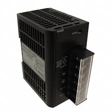
MODEL- MODULE POWER SUPPLY P14 CJ1W-PA202 OMRON
DELIVERY TIME : 1-2 WEEKS Type of module Power supply Type of voltage (input voltage) AC Power output 14 W Input voltage at AC 50 Hz 85-264 V Product Height (unpacked) 90 mm Product Width (unpacked) 45 mm Product Depth (unpacked) 81.6 mm Product Weight (unpacked) 200 g
Rs. 6,500.00
-
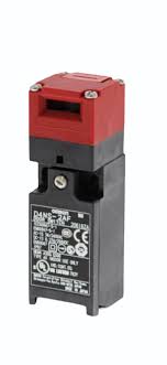
MODEL-LIMIT SWITCH D4NS-1AF OMRON
Door switch type Key-operated Guard-lock Material housing Resin Material head Resin Ambient temperature (operating) -30-70 °C Direction of operation Adjustable Door contacts NC 1 Door contacts NO 1 Switch action Slow action Make before break LED indicator Connection method Terminal block Cable length 0 m Degree of protection (IP) IP67 Conduit size PG13.5 Number of conduits 1 Shape Cuboid Overall length of sensor 96 mm Height of sensor 30 mm Width of sensor 31 mm
Rs. 1,150.00
-
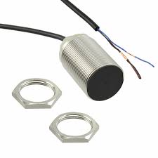
MODEL-PROXIMITY SENSOR E2B-M30KS15-WP-B1 2M MAKE OMRON
DELIVERY TIME : 1-2 WEEKS Size M30 Mounting type Quasi-flush Sensing distance 15 mm Output type PNP Operation mode NO Connection method Cable Material housing Brass, nickel plated Cable specifications PVC Cable length 2 m Overall length of sensor 60 mm Thread length 41 mm Degree of protection (IP) IP67
Rs. 1,100.00
-

MODEL-TOUCH SCREEN NS-1000-V2 MAKE OMRON
DELIVERY TIME : 1-2 WEEKS Mounting Type Panel Mount Display Size 4 inch Resolution 1024 x 768 Pixels Control Type Touch Screen Display Colors 65k Memory 512Mb Communication rs232/usb/ethernet weight 300-1500 gm Omron HMI: Omron HMIs are highly functional with several features. Omron Compact Series: Omron NB Series HMI:NB series has everything you will need for creating applications for a wide range machines and in many industries, for example, packaging, food, plastics and textiles. From a simple lid placing or loading/unloading machine right up toan in-line filling or sealing /labeling packaging machine. More than 65,000 display colors TFT, color touch-screen for all models, Available in sizes ranging from 3 to 10 inches,Long-life LED backlight, Serial, USB or Ethernet communication,USB memory stick support. NB3Q-TW01B, NB3Q-TW00B, NB5Q-TW00B, NB5Q-TW01B, NB7W-TW00B, NB7W-TW01B, NB10W-TW01B, Omron Advance Series: Omron NA and Omron NS Series:An HMI that is dynamic, intuitive and predictive makes industrial machines more attractive and competitive. Our Sysmac HMI enables faster, more efficient control and monitoring and a more natural, proactive relationship between operator and machine.Log large amounts of data using a personal computer. Data can be logged through background processing, with up to 160,000 points stored in one file. The logged data is stored in CSV format, and data can be displayed on data log graphs. NA5-15W101S, NA5-15W101B, NA5-12W101S, NA5-12W101B, NA5-9W001S, NA5-9W001B, NA5-7W001S, NA5-7W001B, NA-15WATW01, NA-12WATW01, NA-9WATW01, NA-7WATW01, NS5-MQ10-V2, NS5-MQ10B-V2, NS5-MQ11-V2, NS5-MQ11B-V2, NS5-SQ10-V2, NS5-SQ10B-V2, NS5-SQ11-V2, NS5-SQ11B-V2, NS5-TQ10-V2, NS5-TQ10B-V2, NS5-TQ11-V2, NS5-TQ11B-V2, NS8-TV00-V2, NS8-TV00B-V2, NS8-TV01-V2, NS8-TV01B-V2, NS10-TV00-V2, NS10-TV00B-V2, NS10-TV01-V2, NS10-TV01B-V2, NS12-TS00-V2, NS12-TS00B-V2, NS12-TS01-V2, NS12-TS01B-V2, NS15-TX01S-V2, NS15-TX01B-V2, NSH5-SQR10B-V2, NSH5-SQG10B-V2, Omron Industrial PC Series: Omron NY Industrial PC Series:NY Industrial PC has been designed from first principles to be powerful, reliable and scalable, making it ideally suited to visualization, data handling, measuring and controlling. We've simplified the design and build to eliminate faults caused by complexity and, with other unique design features, to maximize uptime and reduce costs. NYP17-313K1-12WC1000, NYP35-30370-12WC1000, NYP2C-30370-12WC1000, NYP2A-20460-12WC1000, NYP17-313K1-15WC1000, NYP35-30370-15WC1000, NYP2C-30370-15WC1000, NYP2A-20460-15WC1000, NYP2A-20460-15WC1000, NYP35-30370-19WC1000, NYP2C-30370-19WC1000, NYP2A-20460-19WC1000,
Rs. 99,120.00
-

MODEL-THROUGH BEAM SENSOR, MODEL NO E3T-FT12 MAKE OMRON
DELIVERY TIME : 1-2 WEEKS Ultrathin Photoelectric Sensor with Built-in Amplifier, Through-beam type, Sensing distance: 500 mm, NPN output, Dark-ON, Red light, M2 mounting, Pre-wired model, 2 m Sensing method Through-beam type Sensing distance 500 mm Light source Red LED (650 nm) Connection method Pre-wired models
Rs. 7,956.08
-
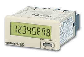
MODEL-COUNTER H7EC-NV MAKE OMRON
DELIVERY TIME : 1-2 WEEKS Small economic counter that is easier to see and easier to use.[Features]·Compact economy counter with improved visibility and ease of use· Realizes large display with 8.6 mm character height. The counter can count up to 8 digits·Series of backlit types with an emphasis on visibility·With a key protect switch to prevent erroneous operation of the reset key·In addition to the conventional light gray case color, a black type has been added to the series· Front part compatible with NEMA4. The main body can be reused by replacing the battery·Adopted finger protection structure compliant with VDE0106 Prat100・ Obtained safety standards UL and CSA·EN61010-1 Contamination Degree 2 / Overvoltage Category III compliant, EMC standard (EN61326-1) compliant Features H7E◯-N external appearance Standard Type / Type With Backlight Type Standard Type Type WithBacklight Mounting Method Embedded Mounting Operation Method Addition Display Method LCD (numerical display by liquid crystal) (character height 8.6 mm) (displayed with zero suppression)*1 Recovery Method External Reset / Manual Reset Number Of Digits 8 Digits Count Input Non-Voltage Input Voltage Input Free Voltage Input Voltage Input 4.5 to 30 V DC 24 to 240 V AC / V DC 4.5 to 30 V DC Maximum Counting Speed 30 Hz / 1 kHz 20 Hz 30 Hz / 1 kHz External Color LightGray Format ◎ Series H7EC-N *2 ◎ Series H7EC-NV *2 ◎ Series H7EC-NFV ◎ Series H7EC-NV-H *3 Black Format ◎ Series H7EC-N-B *2 ◎ Series H7EC-NV-B *2 ◎ Series H7EC-NFV-B ◎ Series H7EC-NV-BH *3 Accessories Waterproof packing, adapter for embedded mounting (Y92F-34) *1. Zero suppression: Zeros are not displayed to increase readability (e.g., "0000008.2" -> "8.2").* 2. For the mark format, a model without a reset key on the front is available as a special option. (In these cases, "-300" is attached to the end of the format.) Please inquire for details.* 3. To turn ON the backlight, it is necessary to externally supply 24 V DC (0.3 W max.).Note: A special option whereby insulating sheets for batteries are not inserted is available. (In these cases, "-350" is attached to the end of the format.) Please inquire for details. Standard Type Mounting Method Embedded Mounting Operation Method Addition Display Method LCD (numerical display by liquid crystal) (character height 8.6 mm) (displayed with zero suppression)*1 Recovery Method External Reset / Manual Reset Number Of Digits 7 digits Time Display 0.0 h to 999,999.9 h / 0.0 h to 3,999 d 23.9 h (switchable) Timing Input Non-Voltage Input Voltage Input Free Voltage Input 4.5 to 30 V DC 24 to 240 V AC / V DC *3 External Color LightGray Format ◎ Series H7ET-N *2 ◎ Series H7ET-NV *2 ◎ Series H7ET-NFV *2 Standard Price (¥) 5,950 6,900 7,250 Black Format ◎ Series H7ET-N-B *2 ◎ Series H7ET-NV-B *2 ◎ Series H7ET-NFV-B *2 Standard Price (¥) 5,950 6,900 7,250 Accessories Waterproof packing, adapter for embedded mounting (Y92F-34), unit sticker *1. Zero suppression: Zeros are not displayed to increase readability (e.g., "0000008.2" -> "8.2").* 2. For the mark format, a model without a reset key on the front is available as a special option. (In these cases, "-300" is attached to the end of the format.) Please inquire for details.* 3. To turn ON the backlight, it is necessary to externally supply 24 V DC (0.3 W max.).Note: A special option whereby insulating sheets for batteries are not inserted is available. (In these cases, "-350" is attached to the end of the format.) Please inquire for details.
Rs. 3,200.00
-
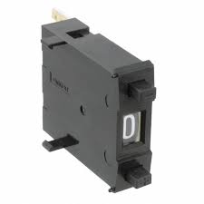
MODEL-PATTERN SELECTOR SWITCH A7PS-206-1 MAKE OMRON
DELIVERY TIME : 1-2 WEEKS [Features]· A dust-proof, easy-to-configure, push-in type with large easily visible text.· Configure via an easy-to-operate push method. Displays large, easily viewable alpha-numeric characters.· The window on the sealed plate prevents dust from infiltrating the display. Model A7PS A7PH Switching capacity (resistive load) 50 VAC or 3.3 to 28 VDC1 mA to 0.1 A 125 VAC or 3.3 to 28 VDC10 μA to 0.15 A Continuous carry current 1 A max. 3 A max. Contact resistance 300 mΩ max. Insulationresistance Between non-connected terminals 10 MΩ min. (at 500 VDC) 100 MΩ min. (at 500 VDC) Between terminal andnon-current carrying part 1,000 MΩ min. (at 500 VDC) Dielectricstrength Between non-connected terminals 600 VAC, 50/60 Hz for 1 min Between terminal andnon-current carrying part 1,000 VAC, 50/60 Hz for 1 min Vibration resistance 10 to 55 Hz, 1.5-mm double amplitude for 2 hours min. Shock resistance 490 m/s2 min. Durability Mechanical 100,000 operations min. 2,000,000 operations min. Electrical 50,000 operations min. 1,000,000 operations min. Ambient temperature Operating: -10°C to 65°C Ambient humidity Operating: 45% to 85% Max. operating force 6.37 N max.
Rs. 750.00
-

MODEL SENSOR MAKE OMRON MODEL - ZX1-LD300A61, SMART SENSOR , 10-30V DC , CLASS-2
DELIVERY TIME : 1-2 WEEKS A resolution of 0.002 mm that’s suitable for simple measurements. • Stable measurements for any type of workpiece. • Models available with four different distance specifications. • Long-distance model for up to 1,000 mm. • Robot cable that can be safely used even with moving parts.
Rs. 53,100.00
-

MODEL-MODULE LINK B7AS-T3BS LINK TERMINAL MAKE OMRON
DELIVERY TIME : 1-2 WEEKS specifications description Model No B7AS-T3BS Color Cream Type of Product Link Terminal Width (mm) 177.8 mm Series B7AS Height (mm) 152.4 mm Depth (mm) 177.8 mm Weight 1 lbs Width 7 inch
Rs. 24,520.60
-
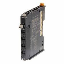
MODEL-POWER CARD FOR PLC NX-PF0730
DELIVERY TIME : 1-2 WEEKS I/O system NX I/O Bus Type of module Power feed I/O connection type Push-in Number of I/O connectors 1 Detachable I/O connector Suitable for safety functions SIL according to IEC 61508 None Number of IOV (V+) terminals 4 Number of IOG (V-) terminals 4 Number of FG terminals 0 Degree of protection (IP) IP20 Product Height (unpacked) 104.5 mm Product Width (unpacked) 12 mm Product Depth (unpacked) 80.1 mm Product Weight (unpacked) 65 g
Rs. 3,800.00


Launching Soon: Our Brand New APP

Important Links
