Products Under 6999
-
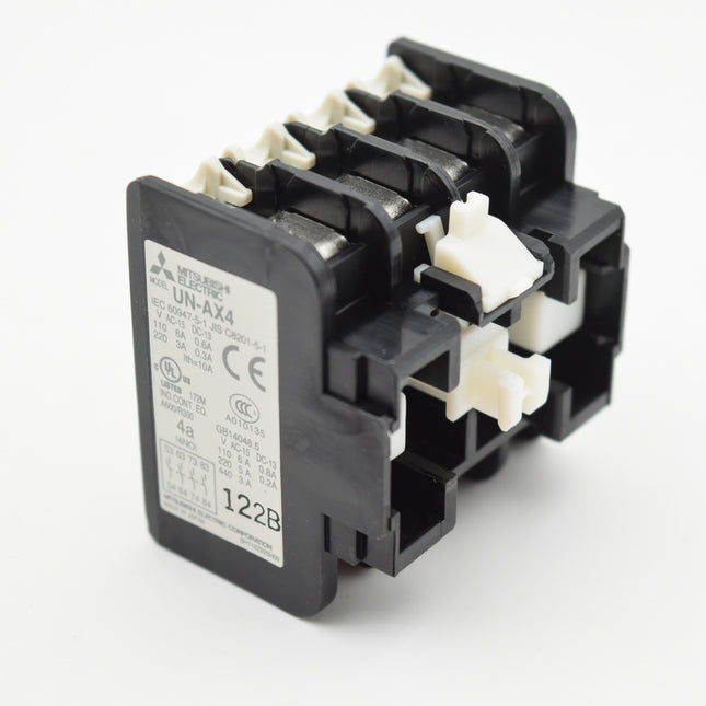
MODEL-AUXILIARY CONTACT FOR MPCB UT-MAX MAKE MITSUBISHI
DELIVERY PERIOD : 1- 2 WEEKS The "MODAL-AUXILIARY CONTACT" for a Mitsubishi UT-MAX make Motor Protection Circuit Breaker (MPCB) refers to an auxiliary contact block that provides additional contacts (usually one or more normally open or normally closed contacts) for signaling or control purposes in a motor control circuit. These auxiliary contacts are electrically separate from the main contacts of the MPCB and are used to interface with other control devices or monitoring systems. Here's a more detailed explanation: Function: Auxiliary contacts are used to signal the status of the MPCB (e.g., tripped, closed, open) to other control or monitoring systems. Types: They can be either normally open (N.O.) or normally closed (N.C.). Connection: They are typically front-mounted and electrically isolated from the main contacts of the MPCB. Application: They can be used to trigger alarms, interlock other devices, or provide feedback to a control system. Mitsubishi UT-MAX: The UT-MAX series from Mitsubishi Electric is a line of MPCBs that utilize these auxiliary contacts. The auxiliary contact blocks, such as the UT AX4 and UT AX2, are designed to be compatible with this series. Example: A common application is to use an N.O. auxiliary contact to signal that the MPCB has tripped, which can then be used to shut down other equipment in the circuit. In essence, the auxiliary contact is an additional feature of the MPCB that extends its functionality by providing feedback or control signals to other parts of the system.
Rs. 2,832.00
-
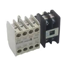
MODEL-AUXILIARY CONTACT FOR MPCB UT-MAL MAKE MITSUBISHI
DELIVERY PERIOD : 1- 2 WEEKS The "MODEL-AUXILIARY CONTACT FOR MPCB UT-MAL MAKE MITSUBISHI" refers to an auxiliary contact unit, specifically designed for Mitsubishi Electric's Motor Protection Circuit Breakers (MPCB) of the UT-MAL series. These auxiliary contacts are used to provide additional signaling or control functionality by indicating the status (open or closed) of the MPCB's main contacts. Here's a breakdown: MPCB (Motor Protection Circuit Breaker): A specialized circuit breaker designed to protect electric motors from various electrical faults like overloads and short circuits. UT-MAL: A specific series or model of Mitsubishi Electric's MPCBs. Auxiliary Contact: A small switch mechanically linked to the main contacts of the MPCB. It opens and closes along with the main contacts, providing a way to remotely monitor or control other circuits. Mitsubishi Electric: A well-known manufacturer of electrical and electronic equipment, including MPCBs and their accessories. In essence, the UT-MAL auxiliary contact unit allows you to: Monitor the MPCB's status: For example, you can use it to signal whether the motor is running or stopped. Interlock other circuits: You can use the auxiliary contact to prevent other devices from operating when the motor is not running, or vice versa. Specific models mentioned in the search results: UT-AX4 2A2B: A Mitsubishi Electric auxiliary contact unit with 2 normally open (NO) and 2 normally closed (NC) contacts. UT-MAXLL 1B: A Mitsubishi Electric auxiliary contact unit with 1 NC contact. UT-MAL 1a, UT-MAL 1b: Possible auxiliary contact units for the UT-MAL MPCB series, with 1 NO and 1 NC contact, respectively. Where to find more information: Mitsubishi Electric's website: You can often find detailed specifications and ordering information for their products on their official website. Technical documentation: Look for the technical catalogs or manuals for the UT-MAL series of MPCBs, which may contain details about compatible auxiliary contact units.
Rs. 2,400.00
-

MODEL-OUTPUT CARD MITSUBISHI FX2N-16EYT
DELIVERY PERIOD : 1-2 WEEKS Specification Value Series MELSEC-F SERIES Type FX2N Occupied I/O Points on PLC 16 Depth (mm) 87 Weight (kg) 216 Width (mm) 40 Height (mm) 90 Power Supply (V) 24 Current Type DC Integrated Digital Outputs 16 Output Type TRANSISTOR Output Logic SINK Talk to Our Engineer for Programmable Logic Controller FX2N-16EYT with exclusive offers. Core System Specifications of FX2N-16EYT are MELSEC-F SERIES FX2N PLC Base Unit at the best prices. This unit features 16-occupied I/O points with ensuring efficient control in industrial automation. It has a compact design with a depth of 87 mm, width of 40 mm, and height of 90 mm, making it space-efficient. The lightweight build of 216 kg allows easy installation. Powered by a 24V supply, it operates reliably in various conditions. The unit includes 16 integrated digital outputs with a TRANSISTOR output type, providing fast and stable switching. The output logic SINK ensures precise execution, making it ideal for automation needs. Don't Miss Out on a Quote for your requirement of Programmable Logic Controller. Count on us for more economical pricing and more reliable support than other Dealers & Distributors.
Rs. 6,938.40
-
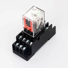
MODEL-RELAY MAKE OMRON MODEL- MY4N-GS COIL VOLTAGE 24VDC 5A 4NO 4NC FOR-92
DELIVERY TIME : 1-2 WEEKS Miniature Power Relay, 4-pole, Single contact, Plug-in terminals, With operation indicator, 24 VDC Coil ratings 24 VDC 36.3 mA Operating indicator LED Contact form 4PDT Contact method Single Contact material Au clad + Ag alloy Contact rated load 220 VAC 3 A (Resistive load)220 VAC 0.8 A (Inductive load (cosφ = 0.4))24 VDC 3 A (Resistive load)24 VDC 1.5 A (Inductive load (L/R = 7 ms)) Terminal structure Plug-in terminal
Rs. 165.70
-
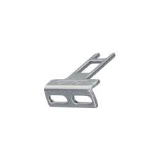
MODEL-LOCK PIN D4DS-K2 OMRON
DELIVERY TIME : 1-2 WEEKS Type Description Select All Category Switches Accessories Manufacturer Omron Automation and Safety Series D4NS Packaging Bulk Part Status Active Accessory Type Operation Key For Use With/Related Products D4NS Series Report Product Information Error View Similar
Rs. 260.80
-
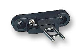
MODEL-LOCK PIN D4DS-K1 OMRON
DELIVERY TIME : 1-2 WEEKS Type Description Select All Category Switches Accessories Manufacturer Omron Automation and Safety Series D4NS Packaging Bulk Part Status Active Accessory Type Operation Key For Use With/Related Products D4NS Series
Rs. 260.80
-
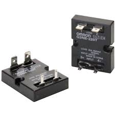
MODEL-SSR G3NE-205TL-US MAKE OMRON
DELIVERY TIME : 1-2 WEEKS Solid State Relay, Phototriac, Applied output load: 5 A at 100 to 240 VAC, Without Zero cross function, #110 input terminals, Certified by UL, CSA, and EN (TUV), Rated input voltage: 24 VDC Product classification For single-phase heater Zero cross function None Operating indicator None Rated voltage 24 VDC Rated load voltage 100 to 240 VAC Load current 0.1 to 5 A (With heat sink at 40 ℃)0.1 to 5 A (Without a heat sink at 40 ℃) Terminal structure Tab terminal (Input: #110, Output: #250)
Rs. 1,500.00
-
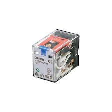
MODEL-MY2N-GS-R RELAY 24VDC MAKE OMRON
DELIVERY TIME : 1-2 WEEKS [Features]· Lead-use eliminated, safe for environment.·With different colors for AC and DC coil tapes, AC and DC specifications are easily identified.·Type MY(S) with a convenient latching lever for circuit check is now also available.·Wiring labor-hours can be shortened by 60% if combined with push-in plus socket Type PYF-□-PU (according to the manufacturer's measured data).·Terminal Shape: Socket / plug-in terminal, PCB terminal.[Applications]·Widely applicable to almost all types of electrical machines and devices.
Rs. 124.72
-
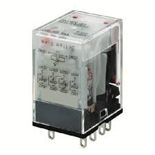
MODEL-MY4N-GS RELAY 24VDC MAKE OMRON
DELIVERY TIME : 1-2 WEEKS Operating indicator LED Degree of protection Closed type (cover) Terminal structure Plug-in terminal Coil Coil ratings 24 VDC 36.3 mA Coil resistance 662 Ω Operate voltage (Set voltage) 80 % max. Release voltage (Reset voltage) 10 % min. Maximum voltage 110 % (23 ℃) Power consumption Approx. 0.9 W Contact Contact rated load 220 VAC 3 A (Resistive load)220 VAC 0.8 A (Inductive load (cosφ = 0.4))24 VDC 3 A (Resistive load)24 VDC 1.5 A (Inductive load (L/R = 7 ms)) Max. contact voltage 250 VAC125 VDC Max. contact current AC: 3 ADC: 3 A Maximum switching power 660 VA (Resistive load)176 VA (Inductive load (cosφ = 0.4))72 W (Resistive load)36 W (Inductive load (L/R = 7 ms)) Contact form 4PDT Contact method Single Contact material Au clad + Ag alloy Performance Contact resistance 50 mΩ max. (Voltage drop method with 5 VDC 1 A) Operating time 20 ms max. (With rated operating power applied, not including contact bounce) Reset time 20 ms max. (With rated operating power applied, not including contact bounce) Maximum operating frequency Mechanical: 18000 time/hourRated load: 1800 time/hour Insulation resistance Between coil and contacts: 100 MΩ min. (at 500 VDC)Between contacts of different polarity: 100 MΩ min. (at 500 VDC)Between contacts of same polarity: 100 MΩ min. (at 500 VDC) Dielectric strength Between coil and contacts: 2000 VAC 50/60 Hz 1 minBetween contacts of different polarity: 2000 VAC 50/60 Hz 1 minBetween contacts of same polarity: 1000 VAC 50/60 Hz 1 min Vibration resistance (destruction) 10 to 55 to 10 Hz, 0.5-mm single amplitude (1-mm double amplitude) Vibration resistance (Malfunction) 10 to 55 to 10 Hz, 0.5-mm single amplitude (1-mm double amplitude) Shock resistance (destruction) 1000 m/s2 Shock resistance (Malfunction) 200 m/s2 Endurance (Mechanical) 100 million operations min. (switching frequency 18,000 operations/h) Endurance (Electrical) 200,000 operations min. (23 ℃, Rated load, switching frequency 1,800 operations/h) Failure rate 1 VDC 1 mA (failure level: Preference value, Switching frequency: 120 operations per minute) Ambient temperature (Operating) -55 to 60 ℃ (with no freezing or condensation) Ambient humidity (Operating) 5 to 85 % Weight Approx. 35 g Mounting method Socket Applicable socket PYF14S/ PYF14T/ PYF-14-PU/ PYF-14-PU-L/ PYFZ-14/ PYFZ-14-E/ PY14/ PY14-Y1/ PY14QN/ PY14QN2/ PY14QN-Y1/ PY14QN2-Y1/ PY14-02
Rs. 618.24
-
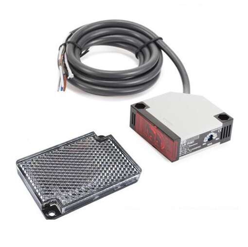
MODEL-PHOTO SENSOR E3JK-R4M1 OMRON FOR ST CONVEYOR
DELIVERY TIME : 1-2 WEEKS Specification Value Sensing Method Retroreflective Sensing Distance 4 m Light Source Red LED Power Supply Voltage 50/60 Hz 12 to 240 VDC ±10%, 24 to 240 VAC ±10 Current Consumption 2 W max. Control Output Relay output: 3 A max. at 250 VAC (cosφ = 1), 10 mA min. at 5 VDC Operation Mode Light-ON mode Response Time 30 ms max. Sensitivity Adjustment Fixed Indicators Light (red) Ambient Temperature Range Operating: –25°C to 55°C (with no icing) Material Plastic The Omron E3JK-R4M1 is a reliable retroreflective photoelectric sensor built for long-distance object detection in general industrial environments. With a sensing range of up to 4 meters, this sensor uses a red LED light source and operates in conjunction with a reflector to detect the presence or absence of objects accurately. It is ideal for applications such as pallet detection, carton counting, and conveyor automation. This sensor supports dual power input: 12 to 240 VDC and 24 to 240 VAC (±10%), allowing flexible installation in both AC and DC systems. The E3JK-R4M1 provides a relay output capable of switching up to 3 A at 250 VAC (cosφ = 1), with a minimum switching capacity of 10 mA at 5 VDC. The sensor operates in Light-ON mode and features a fixed sensitivity setting with a fast 30 ms maximum response time, suitable for moderate-speed automation processes. Power consumption is limited to 2 W max., making it energy-efficient in continuous operation. The red LED status indicator offers clear visibility of sensor activity. Although sensitivity is fixed, the sensor provides reliable performance across a variety of materials and surface finishes when properly aligned with its retroreflective target. The housing is made of durable plastic, and the sensor functions reliably within an ambient temperature range of −25°C to 55°C. It includes essential protections such as insulation resistance, dielectric strength, and tolerance to vibration and shock, ensuring durability in active production environments. With a design focused on simplicity and ruggedness, the Omron E3JK-R4M1 is ideal for OEMs, maintenance engineers, and system integrators looking for dependable long-range sensing in space-efficient form factors.
Rs. 1,350.00
-
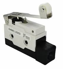
MODEL-LIMIT SWITCH D4MC-2000 OMRON
DELIVERY TIME : 1-2 WEEKS Shape/Structure Enclosed Limit switches ctuator Hinge roller lever 12.7 dia. x 7.5 Frequency 50/60 Hz Contact form SPDT Load General load Ratings (AC): Non-Inductive load Resistive load: 10 A at 125 VAC/10 A at 250 VAC/3 A at 480 VACLamp load (NC): 3 A at 125 VAC/2.5 A at 250 VAC/1.5 A at 480 VACLamp load (NO): 1.5 A at 125 VAC/1.25 A at 250 VAC/0.75 A at 480 VACInductive load: 10 A at 125 VAC/10 A at 250 VAC/2.5 A at 480 VACMotor load (NC): 5 A at 125 VAC/3 A at 250 VAC/1.5 A at 480 VACMotor load (NO): 2.5 A at 125 VAC/1.5 A at 250 VAC/0.75 A at 480 VAC Ratings (DC): Non-Inductive load Resistive load: 10 A at 8 VDC/10 A at 14 VDC/6 A at 30 VDC/0.5 A at 125 VDC/0.25 A at 250 VDCLamp load (NC): 3 A at 8 VDC/3 A at 14 VDC/3 A at 30 VDC/0.4 A at 125 VDC/0.2 A at 250 VDCLamp load (NO): 1.5 A at 8 VDC/1.5 A at 14 VDC/1.5 A at 30 VDC/0.4 A at 125 VDC/0.2 A at 250 VDCInductive load: 6 A at 8 VDC/6 A at 14 VDC/5 A at 30 VDC/0.05 A at 125 VDC/0.03 A at 250 VDCMotor load (NC): 5 A at 8 VDC/5 A at 14 VDC/5 A at 30 VDC/0.05 A at 125 VDC/0.03 A at 250 VDCMotor load (NO): 2.5 A at 8 VDC/2.5 A at 14 VDC/2.5 A at 30 VDC/0.05 A at 125 VDC/0.03 A at 250 VDC Inrush current NC: 30 A max.NO: 15 A max. Ambient temperature Operating: -10 to 80 ℃ (with no icing) Ambient humidity 35 to 95 % Permissible operating frequency Electrical: 20 operations / 1 minute max.Mechanical: 120 operations / 1 minute max. Contact resistance (Initial value) 15 mΩ max. (initial value for the built-in switch whentested alone) Insulation resistance 100 MΩ min. (at 500 VDC) Dielectric strength Between each terminal of the same polarities: 1,000 VAC 50/60 Hz 1 minBetween each terminal and non-live-metallic part: 2,000 VAC 50/60 Hz 1 min Durability Electrical: 500,000 operations min.Mechanical: 10 million operations min. Vibration resistance Malfunction: 10 to 55 Hz, 1.5 mm double amplitude, Contact opening: 1 ms max. at the free position and the total travel position. Shock resistance Destruction: 1,000 m/s2 max. Degree of protection IP67 Operating Force (OF) Standard value 1.96 N max. Release Force (RF) Standard value 0.39 N min. Movement Differential (MD) Standard value 3 mm max. Over-Travel (OT) Standard value 5 mm min. Operating Position (OP) Standard value 40±1 mm Free Position (FP) Standard value 51 mm max.
Rs. 1,000.00
-
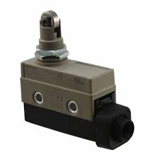
MODEL-LIMIT SWITCH ZCQ2255 MAKE OMRON
DELIVERY TIME : 1-2 WEEKS Shape/Structure Enclosed Limit switches ctuator Panel mount roller plunger 11 dia. x 4.7Stainless sintered alloy roller Frequency 50/60 Hz Contact form SPDT Load General load Ratings (AC): Non-Inductive load Resistive load: 10 A at 125 VAC/10 A at 250 VACLamp load (NC): 3 A at 125 VAC/2.5 A at 250 VACLamp load (NO): 1.5 A at 125 VAC/1.25 A at 250 VACInductive load: 10 A at 125 VAC/10 A at 250 VACMotor load (NC): 5 A at 125 VAC/3 A at 250 VACMotor load (NO): 2.5 A at 125 VAC/1.5 A at 250 VAC Ratings (DC): Non-Inductive load Resistive load: 10 A at 8 VDC/10 A at 14 VDC/6 A at 30 VDC/0.5 A at 125 VDC/0.25 A at 250 VDCLamp load (NC): 3 A at 8 VDC/3 A at 14 VDC/3 A at 30 VDC/0.4 A at 125 VDC/0.2 A at 250 VDCLamp load (NO): 1.5 A at 8 VDC/1.5 A at 14 VDC/1.5 A at 30 VDC/0.4 A at 125 VDC/0.2 A at 250 VDCInductive load: 6 A at 8 VDC/6 A at 14 VDC/5 A at 30 VDC/0.05 A at 125 VDC/0.03 A at 250 VDCMotor load (NC): 5 A at 8 VDC/5 A at 14 VDC/5 A at 30 VDC/0.05 A at 125 VDC/0.03 A at 250 VDCMotor load (NO): 2.5 A at 8 VDC/2.5 A at 14 VDC/2.5 A at 30 VDC/0.05 A at 125 VDC/0.03 A at 250 VDC Inrush current NC: 30 A max.NO: 15 A max. Ambient temperature Operating: -10 to 80 ℃ (with no icing) Ambient humidity 35 to 95 % Permissible operating frequency Electrical: 20 operations / 1 minute max.Mechanical: 120 operations / 1 minute max. Contact resistance (Initial value) 15 mΩ max. (initial value for the built-in switch whentested alone) Insulation resistance 100 MΩ min. (at 500 VDC) Dielectric strength Between each terminal of the same polarities: 1,000 VAC 50/60 Hz 1 minBetween each terminal and non-live-metallic part: 2,000 VAC 50/60 Hz 1 min Durability Electrical: 500,000 operations min.Mechanical: 10 million operations min. Vibration resistance Malfunction: 10 to 55 Hz, 1.5 mm double amplitude, Contact opening: 1 ms max. at the free position and the total travel position. Shock resistance Destruction: 1,000 m/s2 max. Degree of protection IP67 Classification of protection against electric shock Class II Operating Force (OF) Standard value 11.8 N max. Release Force (RF) Standard value 4.9 N min. Pre-Travel (PT) Standard value 1.5 mm max. Movement Differential (MD) Standard value 0.2 mm max. Over-Travel (OT) Standard value 3 mm min. Operating Position (OP) Standard value 47.4±0.8 mm
Rs. 1,700.00


